| Number system | Digits | Base | Examples | Conversion to Decimal |
|---|---|---|---|---|
| Decimal Number System | 0-9 (10) | Base 10 | 12.5 | (1*10^1)+ (2*10^0)+ (5*10^-1) = 12.5 |
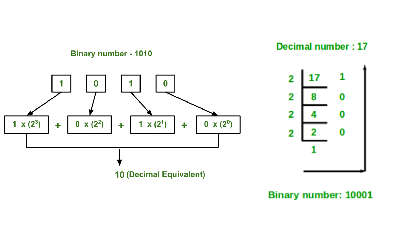
| Binary Number System | 1 & 0 (2) | Base 2 | 100 | (1*2^2)+ (0*2^1)+ (0*2^0) = 4 |
| Octal Number System | 0-7 (8) | Base 8 | 12570 | (1 x 84) + (2 x 83) + (5 x 82) + (7 x 81) + (0 x 80) |
| Hexa Decimal Number System | 0-9 & A-F (16) | Base 16 | 19FDE | (1 x 164) + (9 x 163) + (F x 162) + (D x 161) + (E x 160) (NB: A=10, B=11, C=12, D=13, E=14, F=15) |
In mathematics and digital electronics, a binary number is a number expressed in the base-2
numeral system or binary numeral system, which uses only two symbols: typically "0" (zero) and
"1" (one).
The base-2 numeral system is a positional notation with a radix of 2. Each digit is referred to
as a bit. Because of its straightforward implementation in digital electronic circuitry using
logic gates, the binary system is used by almost all modern computers and computer-based
devices.
The representation of a signed binary number is commonly referred to as the sign-magnitude
notation and if the sign bit is “0”, the number is positive. If the sign bit is “1”, then the
number is negative. When dealing with binary arithmetic operations, it is more convenient to use
the complement of the negative number.
[ 1 bit sign + 7bit number ]

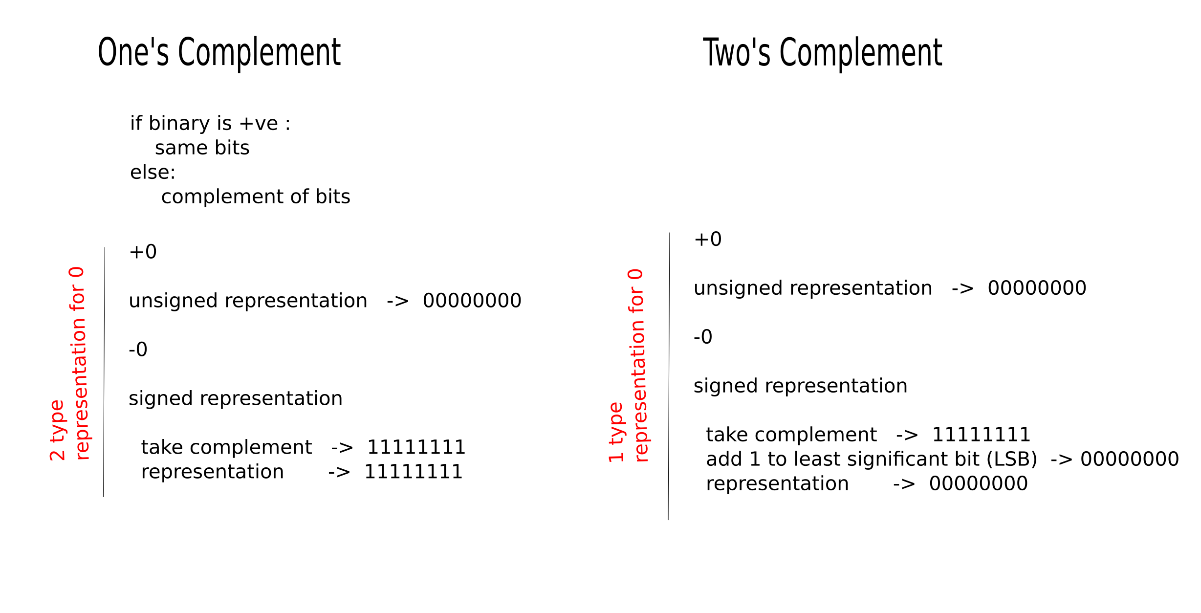
1’s complement of a binary number is another binary number obtained by toggling all bits in
it,
i.e., transforming the 0 bit to 1 and the 1 bit to 0.
Examples:
Let numbers be stored using 4 bits
1's complement of 7 (0111) is 8 (1000)
1's complement of 12 (1100) is 3 (0011)
2’s complement of a binary number is 1 added to the 1’s complement of the binary number.
Examples:
Let numbers be stored using 4 bits
2's complement of 7 (0111) is 9 (1001)
2's complement of 12 (1100) is 4 (0100)
These representations are used for signed numbers.
| One's Complement | Two's Complement |
|---|---|
| two representations of 0 | only one representation for zero |
| It cane be easily obtained using an inverter | It has to be arrived at by first obtaining the 1's complement and then adding one to it. |
| It requires two operations | Only one arithmetic operation is required |
| It is often used in logical manipulations for inversion operation | It is used only for arithmetic applications |
| Represent in Signed magnitude form |
|---|
|
Number = 12 Binary = 1100 8 bit representation : 00001100 sign bit change : 00001100 Number = -12 Binary = 1100 8 bit representation : 00001100 sign bit change : 10001100 |
| Represent signed number in 1's complement form |
| Number = 12 Binary = 1100 8 bit representation : 00001100 not take complement : 00001100 Number = -12 Binary = 1100 8 bit representation : 00001100 take complement : 11110011 |
| Represent signed number in 2's complement form |
| Number = 12 Binary = 1100 8 bit representation : 00001100 not take complement : 00001100 Number = -12 Binary = 1100 8 bit representation : 00001100 take complement : 11110011 add one to LSB : 11110100 |
| Questions - Conversions | |
|---|---|
| Decimal equivalence of signed binary numbers expressed in Signed Magnitude
form eg: 1000000 & 00000001 |
solve 1 answer = - 0 solve 2 answer = +1 |
| Decimal equivalence of signed binary numbers expressed in 1's complement
form eg: 11000000 & 00111111 |
solve 1 -2^7 + 2^6 = -128 + 64 = -64 + 1 (add 1 , bcz signed bit is 1 means -ve) solve 2 2^5 + 2^4 + 2^3 + 2^2 + 2^1 = +63 |
| Decimal equivalence of signed binary numbers expressed in 2's complement
form eg: 11000001 |
solve -2^7 + 2^6 + 2^0 = -128+64+1 = -63 |
The IEEE Standard for Floating-Point Arithmetic (IEEE 754) is a technical standard for
floating-point arithmetic established in 1985 by the Institute of Electrical and Electronics
Engineers (IEEE). The standard addressed many problems found in the diverse floating-point
implementations that made them difficult to use reliably and portably. Many hardware
floating-point units use the IEEE 754 standard.
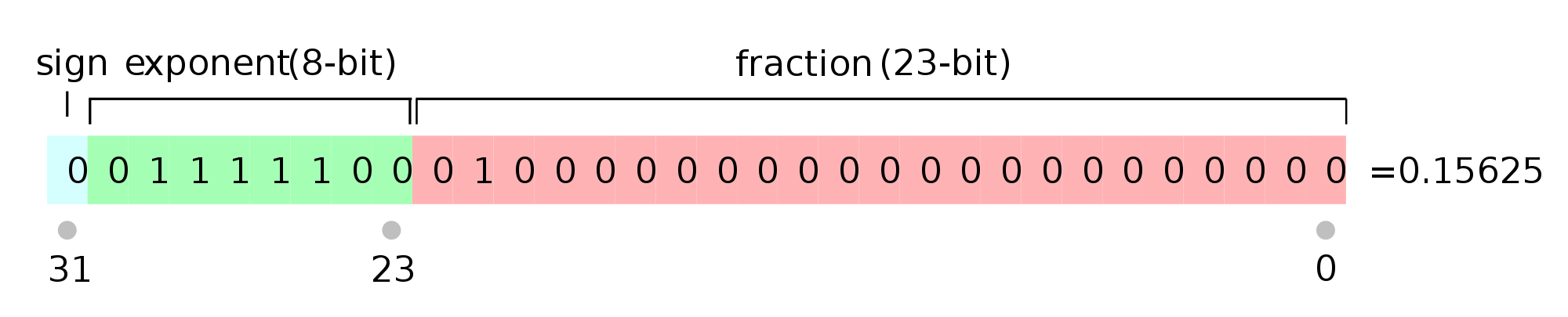
| Precision | Base | Sign | Exponent | Significand |
|---|---|---|---|---|
| Single precision | 2 | 1 | 8 | 23+1 |
| Double precision | 2 | 1 | 11 | 52+1 |
A finite number can also represented by four integers components, a sign (s), a base (b), a
significand (m), and an exponent (e).
Depending on base and the number of bits used to encode various components, the IEEE 754
standard defines five basic formats. Among the five formats, the binary32 and the binary64
formats are single precision and double precision formats respectively in which the base is 2.
| To convert the decimal into floating point, we have 3 elements in a 32-bit floating point representation |
|---|
|
|
Number : 17 Binary : 10001 Normalizing : 1.0001 : (1.001 x 2^4) Sign bit : 0 Exponant : 4 + 127 (bias) = 131 = 10000011 Mantisa : 0001... add zeros. 00010000000000000000000 Representation : (sign exp man) 0 10000011 00010000000000000000000 NB: 1 is omitted from the mantissa's actual storage because it is redundant. |
| To convert the floating point into decimal, we have 3 elements in a 32-bit floating point representation |
|
|
Number : 0 10000011 00010000000000000000000 Sign : +ve Exponant : 131 (10000011) - 127 = 4 Mantisa : 0001 Represetation : + 1.0001 x 2^4 = 10001 =17 |
| More Information |
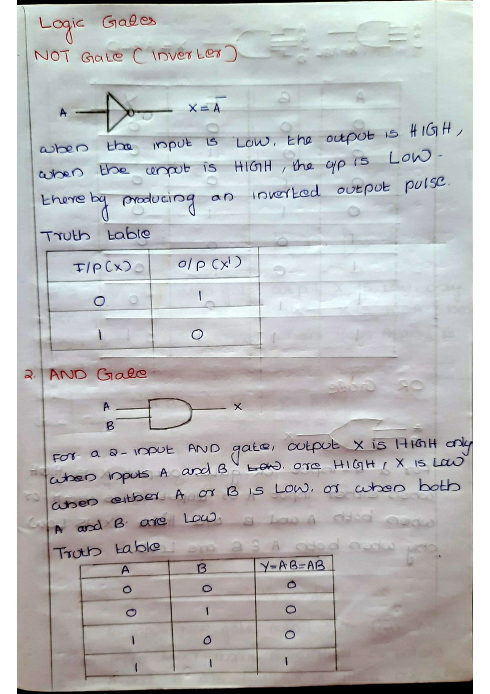
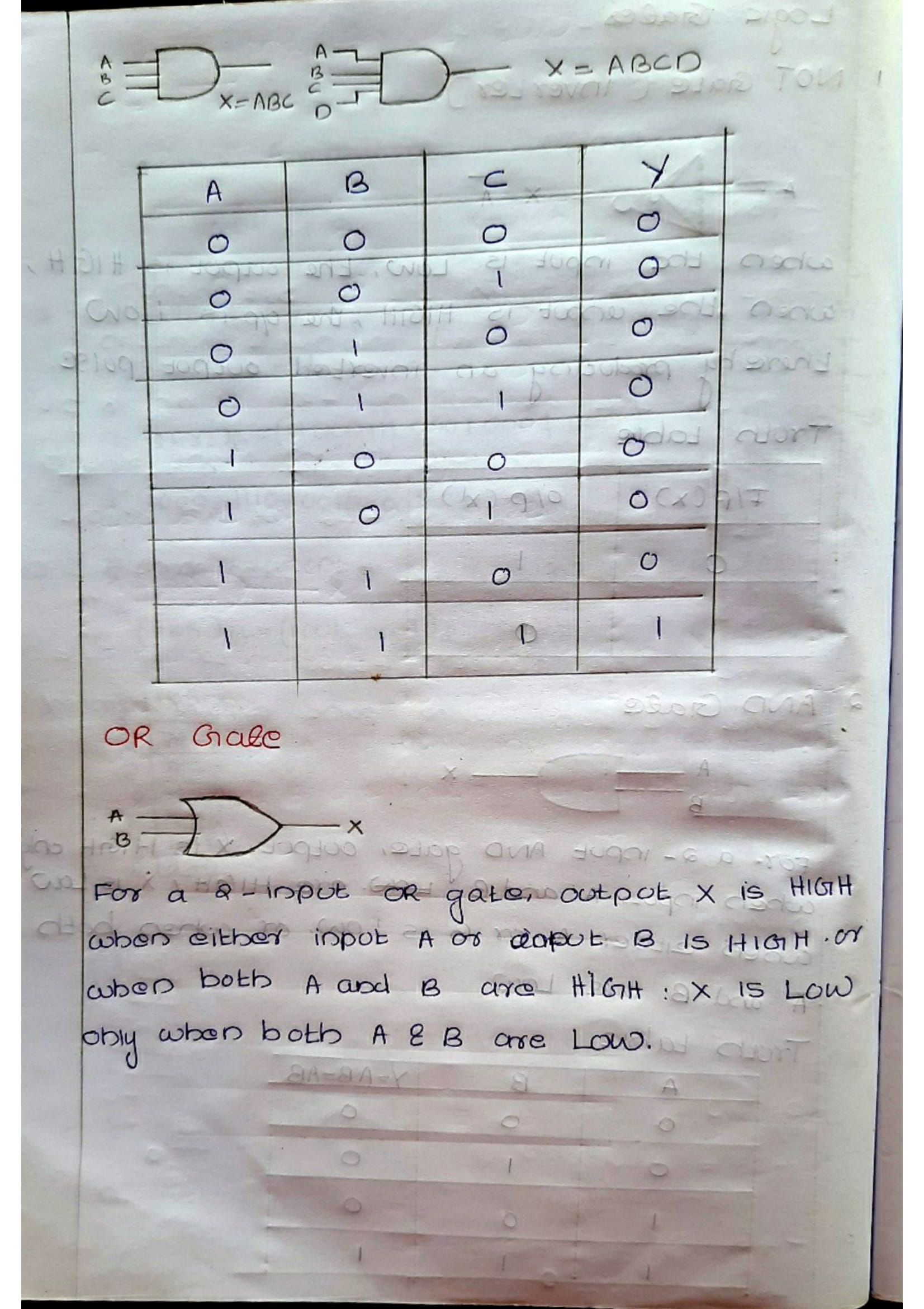
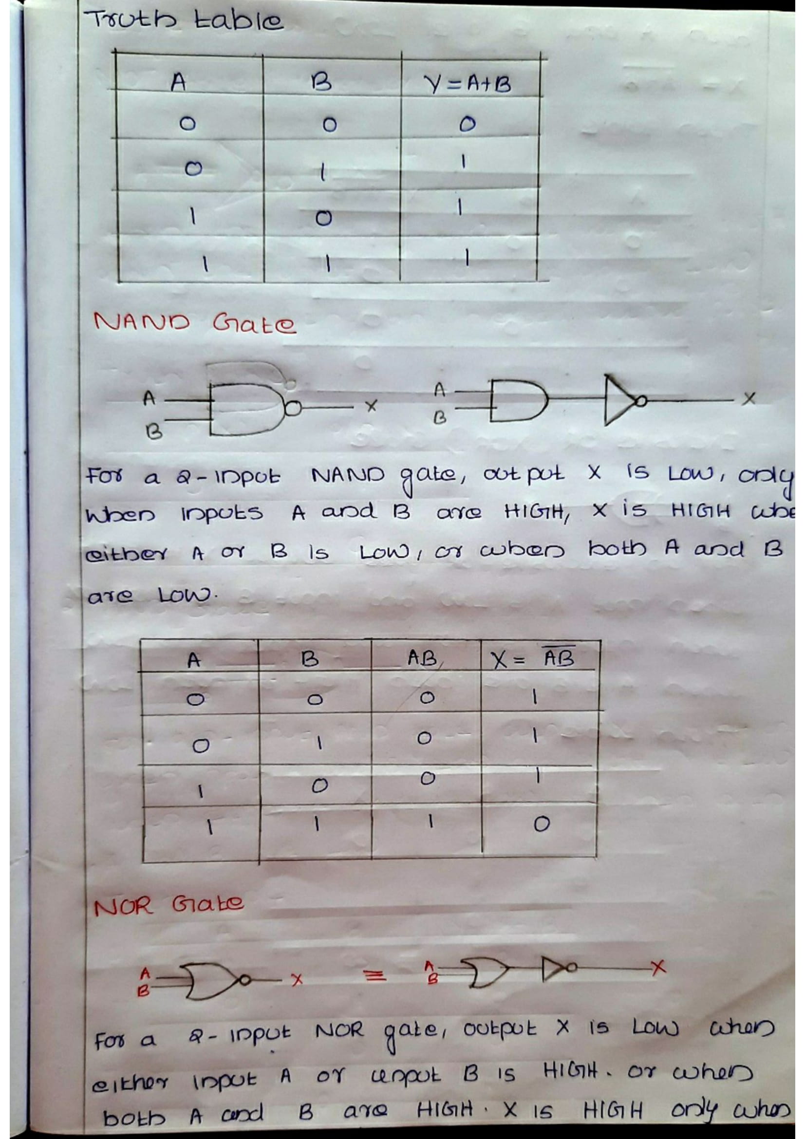
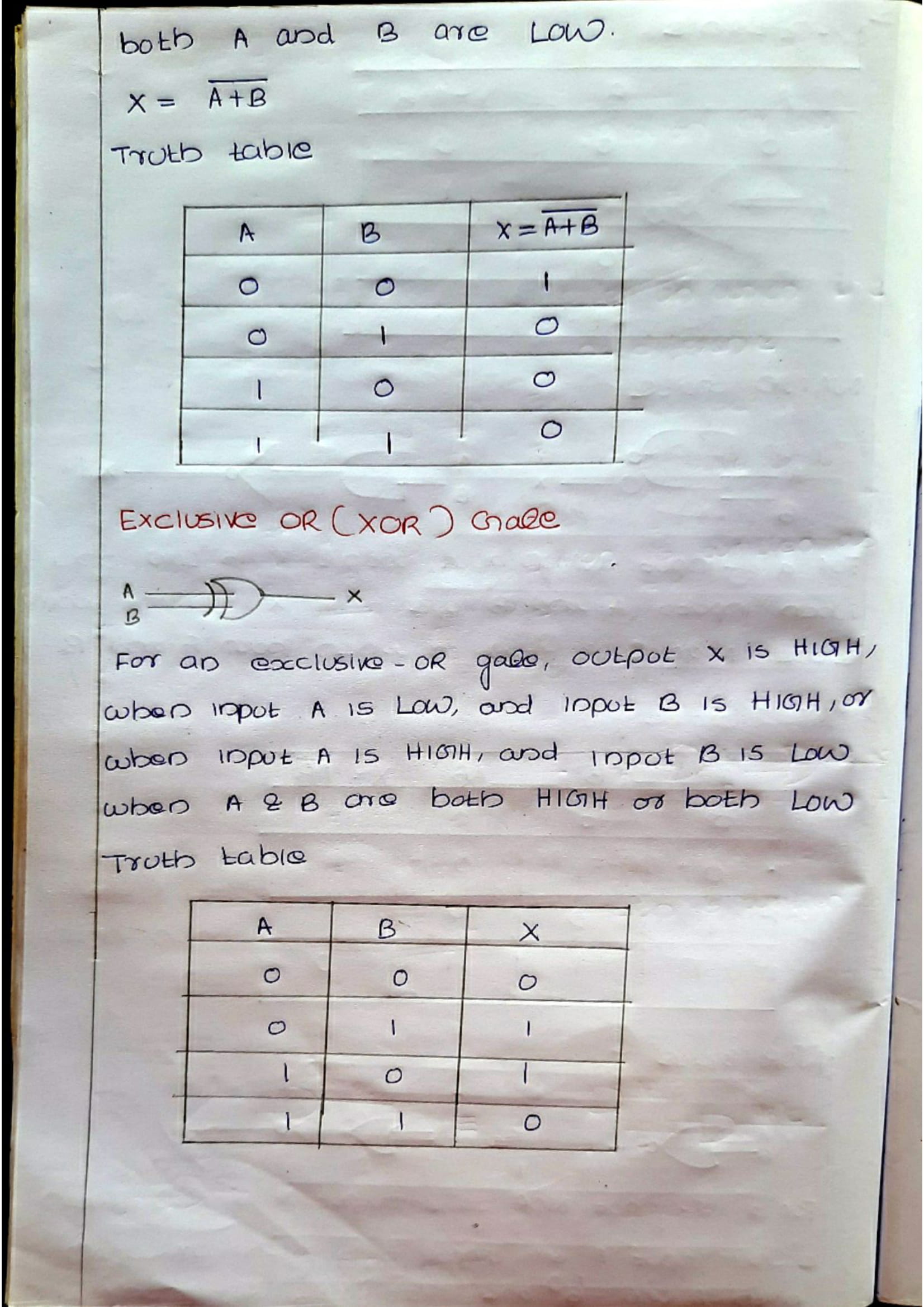
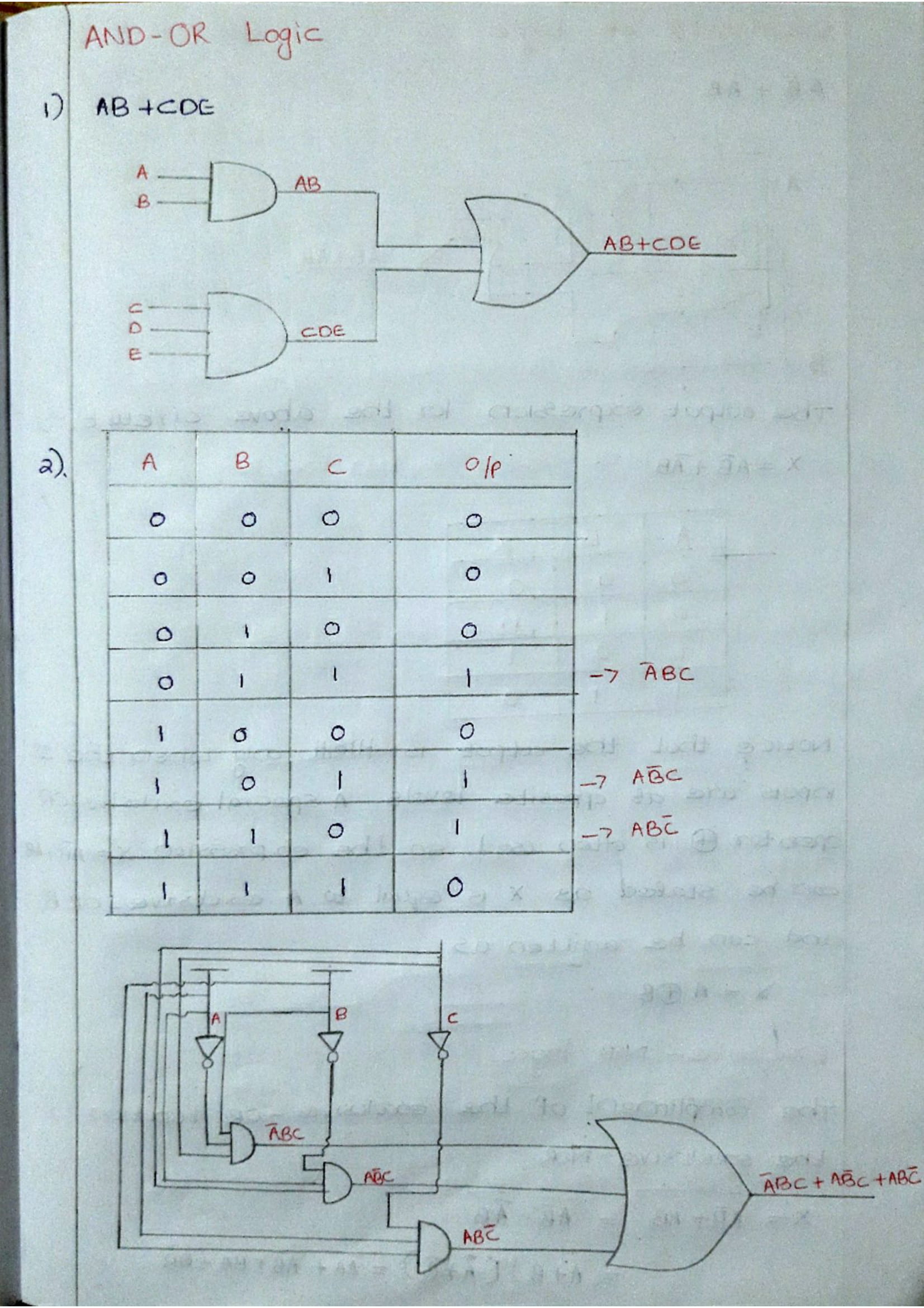
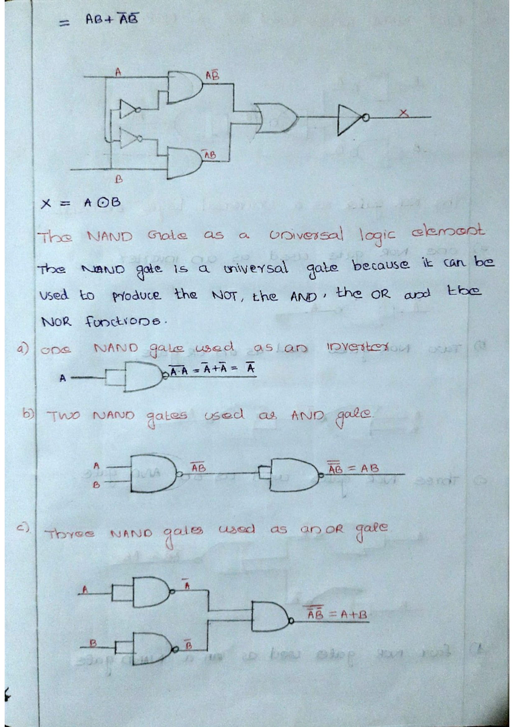
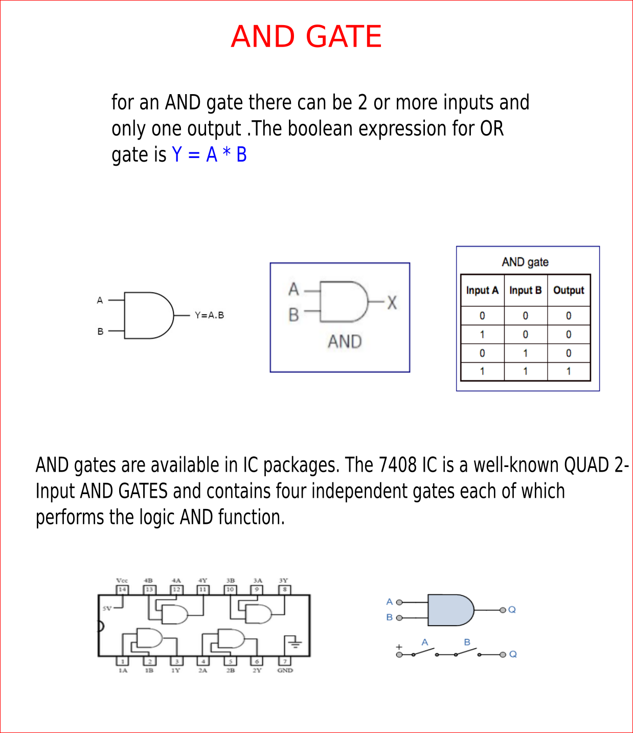
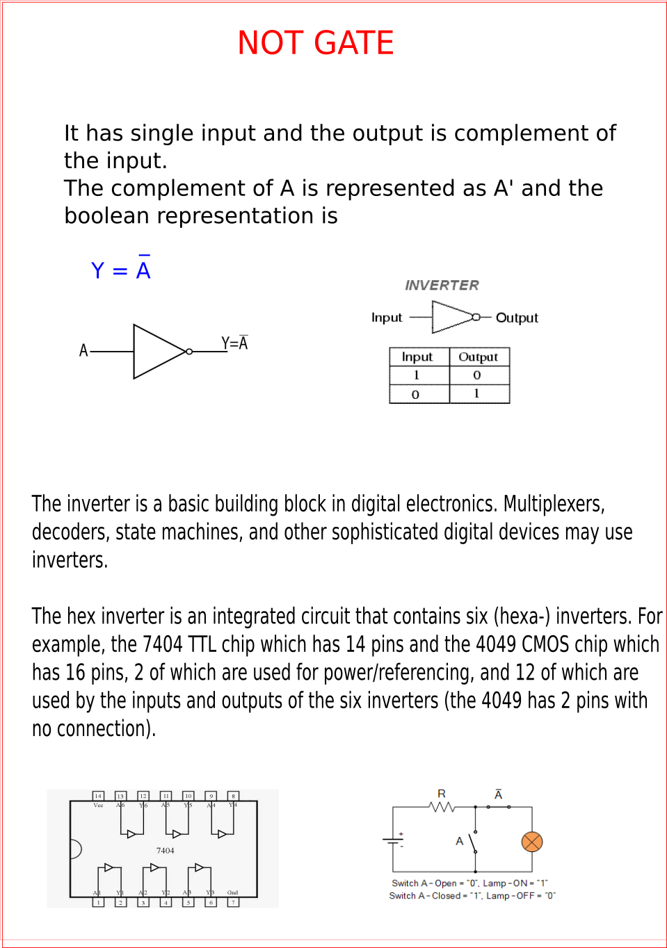
Logic gates are the basic building blocks of any digital system. It is an electronic circuit having one or more than one input and only one output. The relationship between the input and the output is based on a certain logic. Based on this, logic gates are named as AND gate, OR gate, NOT gate etc.

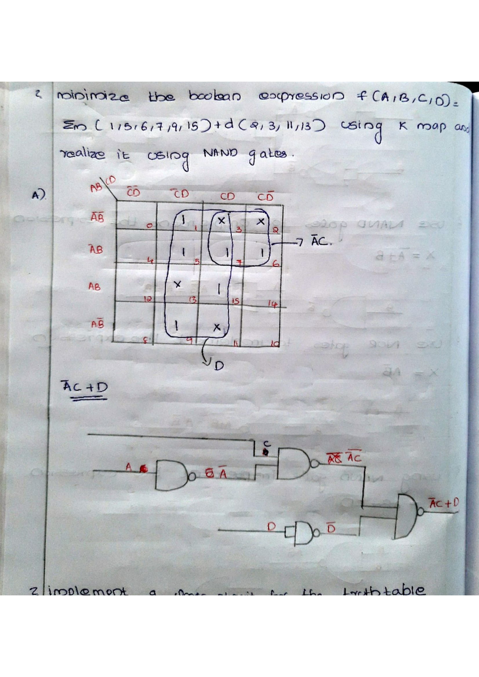
Boolean Algebra is used to analyze and simplify the digital (logic) circuits. It uses only the binary numbers i.e. 0 and 1. It is also called as Binary Algebra or logical Algebra. Boolean algebra was invented by George Boole in 1854.
Boolean Laws| LAWS | Representation |
|---|---|
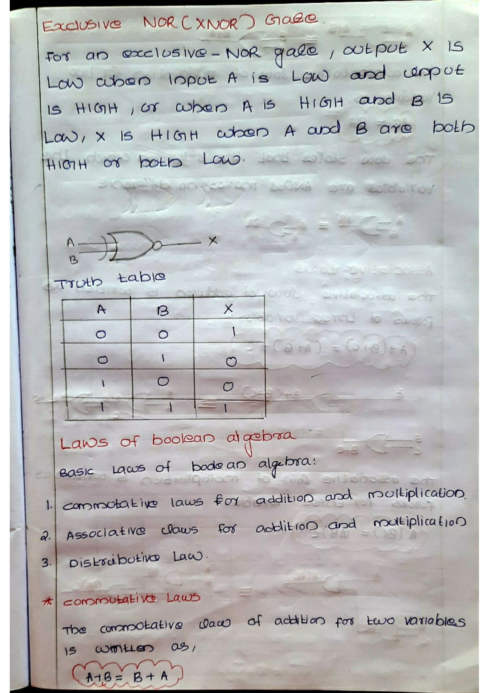
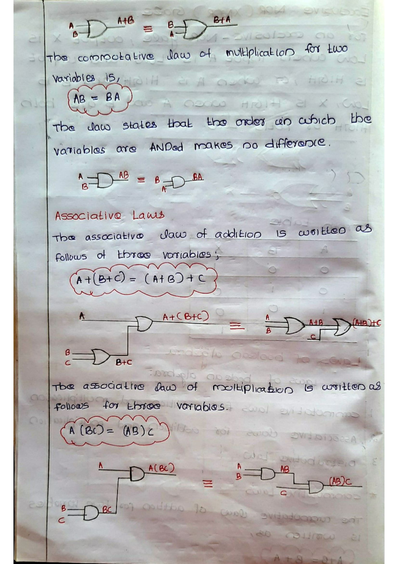
| Commutative law | i) A.B = B.A ii) A+B = B+A |
| Associative law | i) (A.B).C = A.(B.C) ii) (A+B)+C = A+(B+C) |
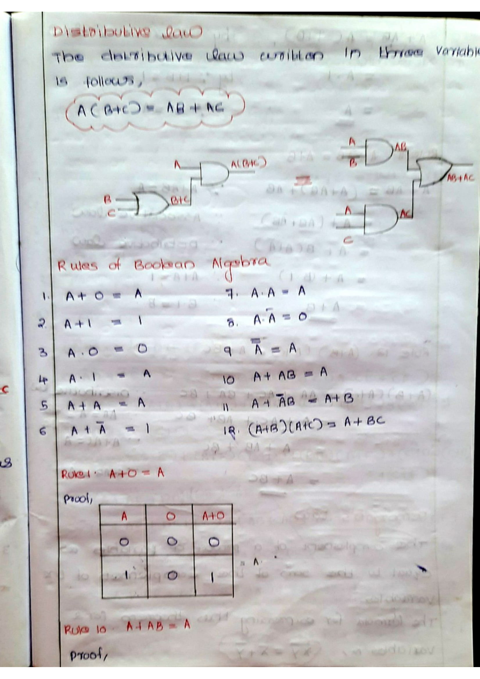
| Distributive law | i) A.(B+C) = A.B + A.C |
| AND law | i) A.0 = 0 ii) A.1 = A iii) A.A = A iv) A.A = 0 |
| OR law | i) A+0 = A ii) A+1 = 1 iii) A+A = A iv) A+A = 1 |
| INVERSION law | Complement of A = A |
| Examples | A + AB = A A + AB = A + B (A+B)+(A+C) = A+BC |
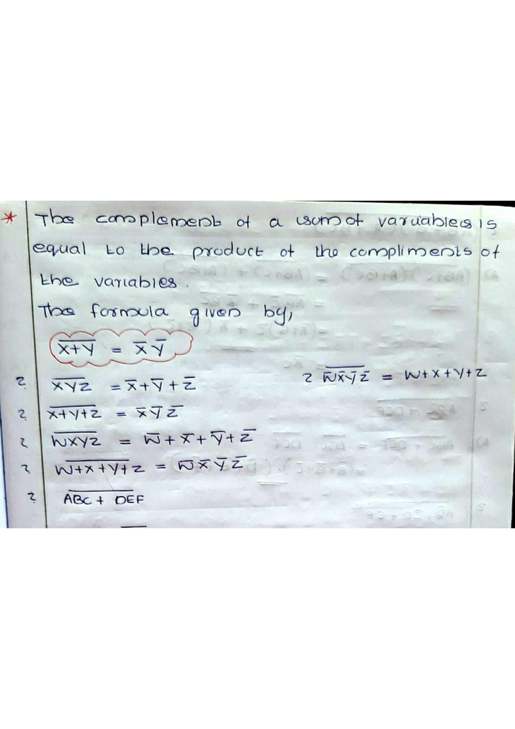
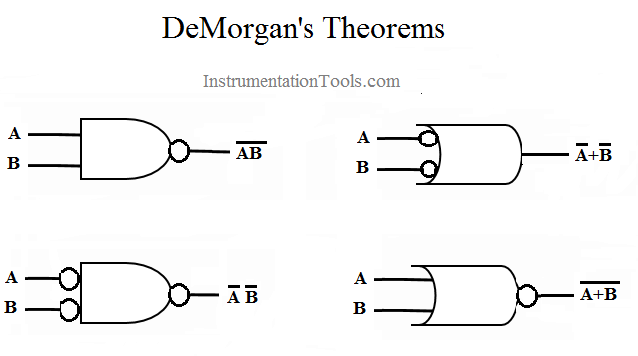
The theorem explains that the complement of the product of all the terms is equal to the sum of the complement of each term. Likewise, the complement of the sum of all the terms is equal to the product of the complement of each term.
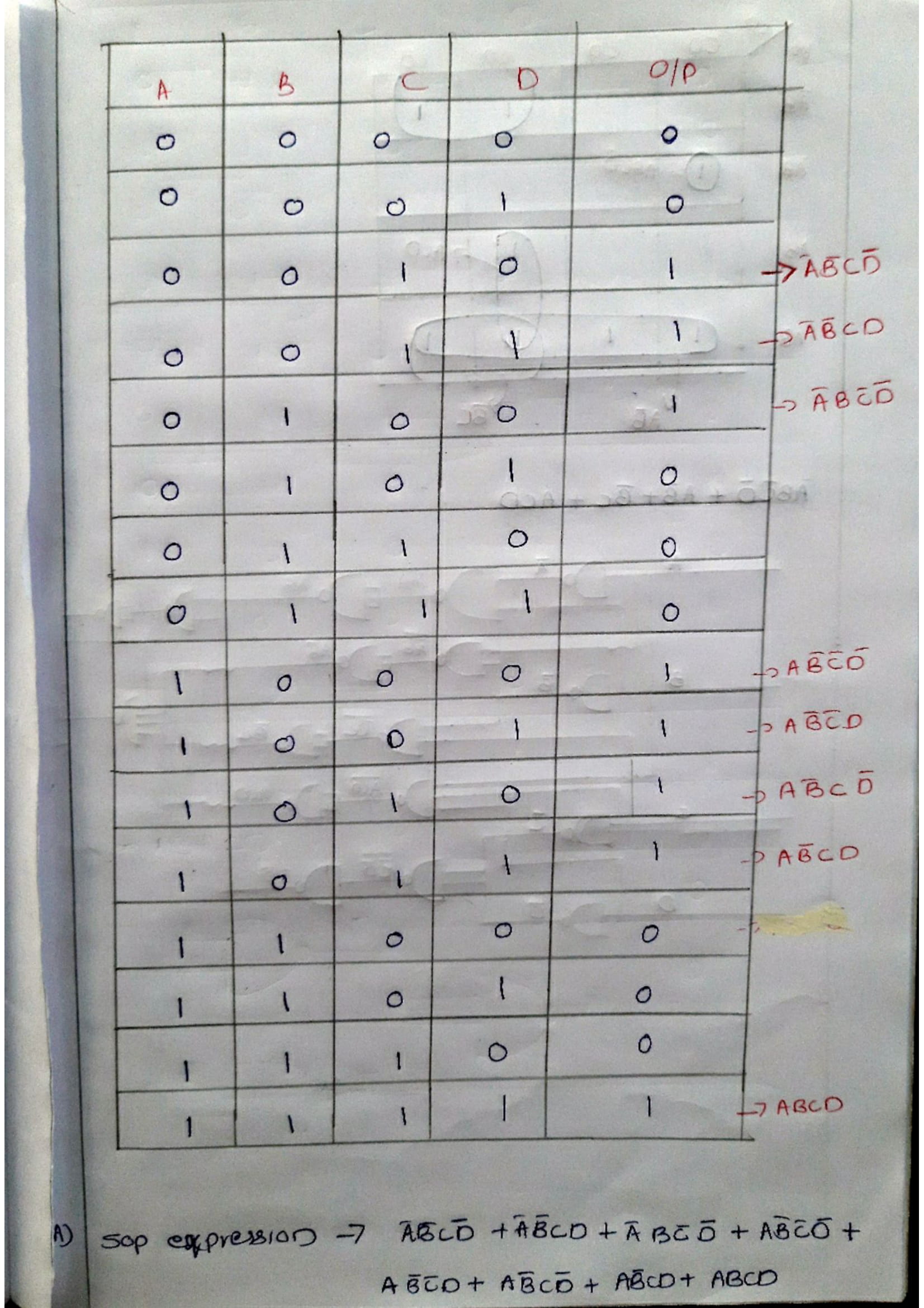
In digital logic, the inputs and output of a function are in the form of binary numbers (boolean
values) i.e., the values are either zero (0) or one (1). Therefore, digital logic is also known
as ‘Boolean logic’. These inputs and output can be termed as ‘Boolean Variables’. The output
boolean variable of a digital signal can be expressed in terms of input boolean variables which
forms the ‘Boolean Expression’.
Representation of Boolean expression can be primarily done in two ways. They are as follows:
If the number of input variables are n, then the total number of combinations in Boolean algebra
is 2n.
If the input variable (let A) value is :
Zero (0) – a is LOW -It should be represented as A’ (Complement of A)
One (1) – a is HIGH -It should be represented as A